Electronic Analytical Balance
Today, if we were to wander around the nation’s industrial facilities and laboratories, we would find electronic balances being used for everything from counting batches of resistors to adjusting the component ratio of epoxy mixtures. Many of these balances are suitable for the most demanding analytical work, while others are less precise but serve many
purposes well. In the following discussion the analytical balance is defined as an instrument with capacities ranging from 1 g to a few kilograms and with a precision of at least one part in 10s of maximum capacity. Many modern electronic balances have a precision of one part in 107 at full capacity, and the accuracy is usually comparable. The inspiration for the modern analytical balance came from a weighing method change suggested by Borda (1).
To overcome the difficulties of unequal arm lengths inherent with the two-pan, equal-arm balance, Borda suggested a method known as substitution weighing to be used in place of transposition weighing. In 1886 a balance was designed and built specifically for substitution weighing, although the modern one-pan substitution balance did not become commonplace until the 1950s. Although these balances are completely mechanical in operation, the optical readout system was usually assisted with a light bulb.
The Analytical Balance and the Mass
UnitBefore looking in detail at the electronic balances, it is worthwhile to consider how mass is determined from a balance weighing and to briefly look at the inner workings of a modern mechanical substitution balance. The reader should keep in mind that of the many forces the balance can respond to, we are only interested in the gravitational and buoyant forces and would like to exclude all others.
First, we must recognize that the balance reading is not the mass of the sample being weighed and therefore is not the desired result. The balance manufacturer has built the balance to indicate so-called apparent mass of the material being weighed. In essence, if the material being weighed has a density of 8.0 g/cm3 at 20 °C anc the air density is 0.0012 g/cm3, then and only then does the balance indicate the mass of the object being weighed. Obviously, these conditions are rarely met, and the balance reading must be corrected to get the desired mass (2).
The important point of the above discussion is that all analytical balances are calibrated by the manufacturers to indicate what is known as “apparent mass vs. 8.0 g/cm3.” In some instances the balance may actually contain a single weight or a set of weights, or a weight may be supplied separately by the balance manufacturer for calibration of the balance. It is from this initial calibration and subsequent recalibrations that the user is tied to the mass unit, directly for standard conditions and by computation for all other conditions.
For many years another apparent mass scale based on this principle had been in use. The basis of this scale was a brass weight whose density was specified to be 8.3909 g/cm3 at 20 °C with an air density of 0.0012 g/cm3. This scale is generally referred to as the “apparent mass vs. brass” scale.
Balance Principles
Today there are two dominant types of electronic balances in use — the hybrid and the electromagnetic force balance. The hybrid balance uses a mix of mechanical and electronically generated forces, whereas the electromagnetic force balance uses electronically generated forces entirely. A brief review of mechanical balance principles is worthwhile before the hybrid and electromagnetic force balances are discussed. In all cases, a null indicator is used to determine when the internal force balances the gravitational force on the sample.
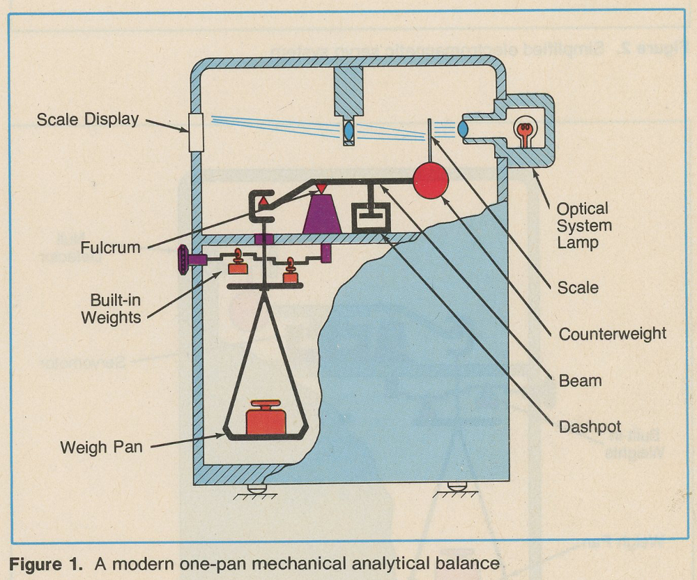
 The Mechanical Balance. The modern mechanical balance is a one-pan, two-knife balance with the applied gravitational force on the pan nearly counterbalanced by a fixed weight built into the balance beam. Any residual inequality of forces causes an angular displacement of the beam. Equilibrium is reestablished by adding or subtracting internal weights.
Figure 1 is a schematic of a typical one-pan mechanical balance. The balance readout is attained by summing the weight dial indications with a beam displacement indicator such as a projected optical scale. Whatever means are used to indicate the angular displacement of the balance beam, the balance is manufactured and calibrated to indicate the same
apparent mass scale as that of the built-in weight. The prominent features are the built-in weights (i.e., mass standards) and beam damping. However, of significance is the constant loading of the balance beam regardless of the sample weight on the pan. This feature provides a constant balance sensitivity; that is, the angular beam displacement in response to a small force change remains constant regardless of pan loading, a characteristic not found in equal-arm balances.
The Hybrid. The hybrid balance is identical to the mechanical balance just described except the balance beam is never allowed to swing through large angular displacements when the applied loading changes. Instead the motion is very limited and when in equilibrium the beam is always restored to a predetermined reference position by a servo-controlled electromagnetic force applied to the beam.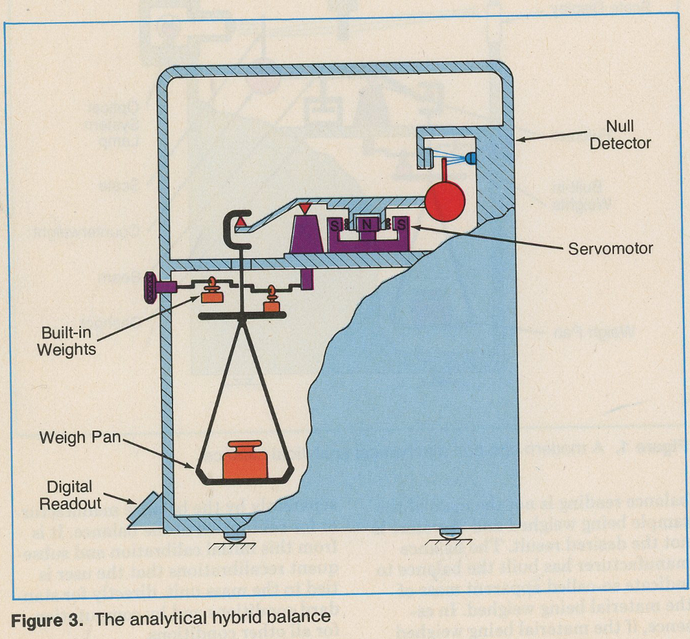
The Electromagnetic Force Balance. The more recent development of the electromagnetic force balance is a radical departure from the past in several ways. First, a magnetic force balances the entire load either by direct levitation or through a fixed-ratio lever system. Second, the loading on the electromechanical mechanism that constitutes the balance is not constant, but varies directly with applied load. Finally, the sensitivity and response are no longer dominated by the dynamics of the balance beam but are largely controlled by the servo system characteristics.
The Servo System
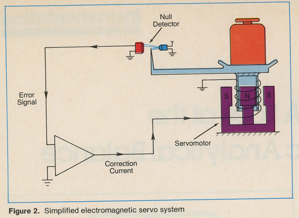
Servo systems differ in classification and design, but a simple explanation of how a balance servo works in principle is given here. The details of the circuitry are omitted since there are many different means to achieve the desired result. There are two distinct electronic approaches to the servo system. In one method a continuous current is driven through the servomotor coil and in the other method the current is pulsed. The latter technique has the advantage of simpler coupling to digital readout indicators, although both systems work well and, from the user’s standpoint, there are many advantages available from the electronic nature of the cell regardless of its internal operation. In an electromagnetic servo system (Figure 2), the force associated with the sample being weighed is mechanically coupled to a servomotor that generates the opposing magnetic force. When the two forces are in equilibrium the error detector is at the reference position and the average electric current in the servomotor coil is proportional to the resultant force that is holding the mechanism at the reference position. When the applied load changes, a slight motion occurs between the fixed and moving portions of the error-detector components, resulting in a very rapid change in current through the coil. The direction and magnitude of this current change are such as to restore the equilibrium condition. The reference or “null” position is usually not arbitrarily chosen, but is selected to allow the flexure pivots to remain in a relaxed state with the beam parallel to the gravitational horizon.
A Closer Look at Electronic Balances
The Hybrid. When the mechanical balance is modified by the addition of servo control and other electronics, as shown in Figure 3, several beneficial things happen. Functionally, the most important change occurs when the balance beam is servoed to a reference or null position. Doing this not only results in an electronic output but also makes knife adjustments and edge quality less critical. Furthermore, other forms of pivots, such as flexural pivots, taut fibers, etc., which are more rugged and economical to manufacture, can then be used in place of knife edges. Like the purely mechanical balance, the balance output from a hybrid balance is the summation of the built-in weights being used for a particular weighing and the restoring force required to hold the beam at the null position. In some balances the output reading indicates both of these in a single digital display, the necessary summing having taken place electronically. The most salient features that distinguish the electronic hybrid from the electromagnetic force cell balance are the still-recognizable balance beam and the built-in weights. Equilibrium is closely approximated by the selected built-in weights so that the forces generated by the servomotor are small. If industry trends continue, the hybrid balance will eventually disappear at capacities much above 1 g, but will probably survive for some time to come at the lower capacities. At these small capacities there is at present a problem of balance precision surpassing the expressed uncertainty of the built-in weights and any external weight sets that may be required
in the use of a balance. Normally the manufacturer will calibrate or adjust these weights to a tolerance comparable to the balance precision. When this is not possible these weights are sometimes viewed merely as tare weights.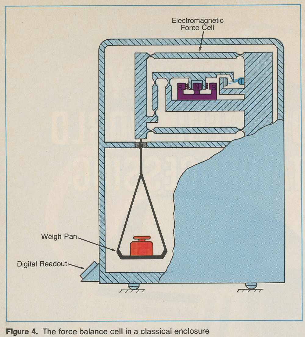
The Force Balance. While the top-loading electronic balance is a familiar sight in many situations, its principle of operation is least understood by most operators. In recent years the force balance principle has also been incorporated into classical enclosures, like those used for the early mechanical balances, as shown in Figure 4. For this reason it is convenient to refer to the electromechanical heart of the balance as the electromagnetic force-balance cell, or simply, the cell. The logic behind having two distinct instrument configurations will become apparent later in the discussion. Like the hybrid balance, one of the cell’s outstanding features is the principle of servoing the mechanical mechanism to a null position. In either configuration the forces generated by the servo motor are much larger than those required for an equivalent-capacity hybrid balance. Of course, the balance beam, if any, no longer resembles its predecessor, and it is always tethered by a parallelogram loading constraint (guides). Unlike the mechanical and hybrid balances that have a counterweight and therefore a compensating buoyant force, the higher precision cells are more reflective of air density changes and may require frequent calibration. Looking first at the top-loading configuration of the weighing cell (Figure 5), we see that the sample to be weighed is loaded on a weight pan and the loading guides prevent torsional forces, caused by off-center loading, from perturbing the alignment of the balance mechanism. These same guides may serve to stabilize the moving portion of the servo motor, or as shown in Figure 5, an additional restraint may perform this task. As previously described, an electromagnetic force is generated to oppose the net gravitational and buoyant force imposed by the mass being weighed. The balance readout is proportional to the amount of current passing through the coil when the equilibrium position is established. The constant of proportionality provides the conversion from current units to apparent mass units. Calibration is performed by the application of a calibrating weight and adjusting the circuitry to indicate the apparent mass of the calibrating weight. Higher precision can be obtained if the weighing pan is placed below the cell rather than above it, as shown in Figure 4. This is due to better axial alignment at the pan hook (minimum off-center loading) and a reduction in servomotor force with a corresponding drop in capacity. Both configurations of the cell require air-draft shielding for high levels of precision. The industry trend is toward the complete elimination of the hybrid balance at the very highest levels of precision and toward increasing capacity.
Benefits and Idiosyncrasies
Because the modern analytical balance is electronic in nature it is very often found with a microprocessor as part of the package. The level of sophistication of these instruments may be very high, and there are many balance functions and idiosyncrasies that are unfamiliar to those who are acquainted only with mechanical balances. Let us examine the electronic capabilities that are inherent to the basic balance and those that may be optional.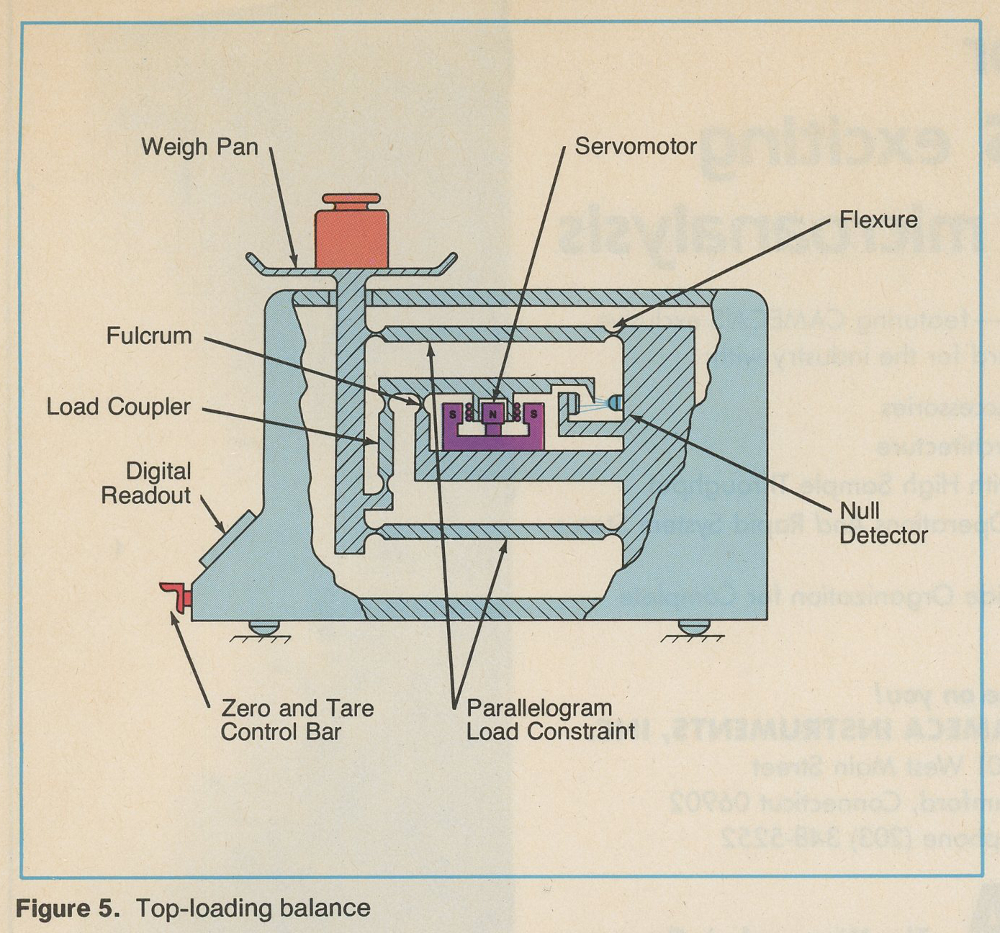
Benefits. It is assumed that all balances have the digital display to indicate “weight” and a means to provide a zero indication when no load is applied to the weigh pan. Beyond these basic features one is apt to find taring control, dual capacity and precision, selectable sampling period, etc. A brief summary of these features follows:
• Taring Control. A means to ignore the indication of a weighing constant, such as a weighing boat, by forcing a zero indication when the boat is placed on the balance pan. Most balances permit taring to 100% capacity.
• Dual Capacity and Precision. This feature allows the balance capacity to be decreased by a predetermined amount with a comparable gain in precision, i.e., a two-for-one balance. The choice of where to place the smaller, more precise range can vary from one balance to another.
• Selectable Sampling Period. The time required for a balance to obtain a reliable indication under ambient conditions may vary from one location to another; therefore provision is made so the user can vary the integration period by a simple circuit change. As the sampling period is lengthened the overall balance weighing cycle is likewise lengthened.
• Filters. Some manufacturers provide electronic filters that eliminate certain portions of the noise spectrum from the servo loop.
• Computer Compatibility. A means to access the balance by an external computer that may range from a simple data transfer such as a BCD output to complete functional control as offered by an RS-232C or IEEE-488 interface bus.
• Computation. A balance option that does computations such as counting, standard deviation calculations or user-programmable computations.
• Environmental Weighing Delay. Some balances have a circuit that protects the user from collecting poor data, due to unusually strong air currents or vibrations, by not displaying the weighing results during these periods. Some balances may have an override capability provided by the manufacturer for the acquisition of data during such periods.
Idiosyncrasies. Some idosyncras of the electronic balance follow. They may present a problem in some applications:
• Weighing Ferromagnetic Material. Ferromagnetic materials may perturb the magnetic field associated with the servomotor, leading to systematic errors in the weighing. This can be checked by moving the material in and around the pan area while looking for large changes in the balance zero reading. An easy remedy is to weigh below the balance pan because magnetic forces fall off rapidly with distance. The above effects would be even more pronounced if one had to weigh magnetic materials.
• Electromagnetic Radiation. Electronic balances may malfunction in the presence of a strong electromagnetic field. This effect may be checked by keying a hand-held radio transmitter near the balance and looking for a change in balance indication.
• Dust Susceptibility. Dust migration (from a dirty environment) into the gap between the pole pieces associated with the permanent magnet and moving coil of the servomotor can cause insidious changes in the balance precision and calibration. When these particles are ferromagnetic the balance may be rendered inoperable. Such environments should be avoided. There may also exist a severe explosion potential in this type of environment, mandating the use of an entirely mechanical balance.
Black Box Comparison
In selecting a particular balance for a task, the following are the familiar specifications to consider along with what has been covered above in detail: capacity, accuracy (agreement with mass scale), precision (reproducibility of a measurement), zero stability, linearity, built-in weight tolerance or calibration accuracy, speed of response, pan size (top-loading balances), temperature coefficient, resolution (least significant figure in the display), and power requirements.
Because all balance manufacturers do calibrate their products to the 8.0 apparent mass scale, any potential user can test these specifications with the appropriate 8.0 laboratory weights. One should keep in mind that the manufacturer has tested the product under the best laboratory conditions and if your laboratory is not as conducive to weighing this will be reflected in the test results.
The analyst should keep in mind that the balance precision attained in the laboratory will usually dominate the measurement error. However, precision errors must be summed with linearity errors and weight calibration errors in determining the measure.
Published in 1982